This article shows how to configure the network from scratch, step-by-step, layer 2 with multi-homing, and Layer 3 EVPN and VXLAN on the SR-Linux platform. It assumes you have a basic knowledge of the mentioned technology, if not, don’t worry. Whenever you need details, you can find links to RFCs to deep dive into a specific network area.
IP Fabric/Underlay Network
IP Fabric in Data Center Network provides a flat architecture offering a 2-tier design. This model consists of spine and leaf switches, where each leaf switch is connected to each spine switch, based on an IP, to deliver Equal Cost Multi-Path (ECMP) load balancing across all available Layer 3 links. This provides a consistent path for east-west traffic, especially for applications built as micro-services.
Network Topology
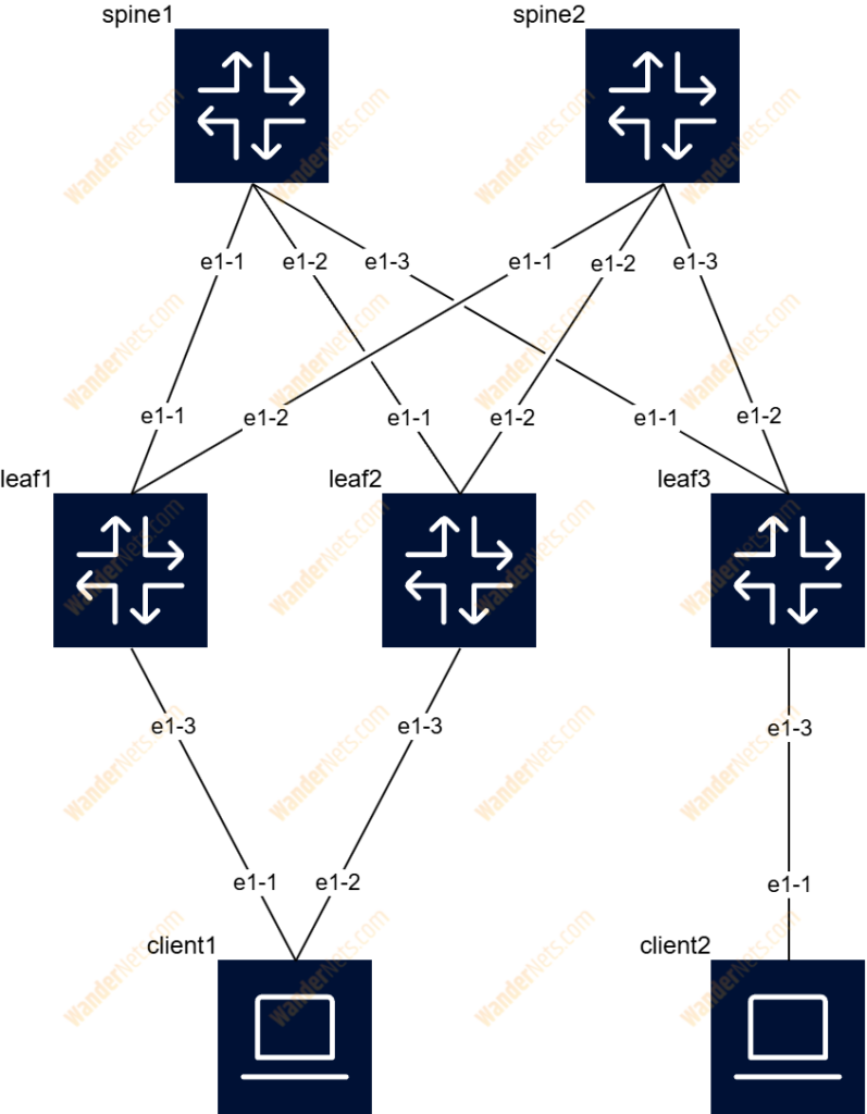
The diagram below shows a simple IP Clos network that contains two spine switches as well as three leaf switches, two of which form an EVPN Multihoming for clients. IP addresses from RFC 5737 were used to build the underlay network and eBGP was selected as the routing protocol.
Topology details:
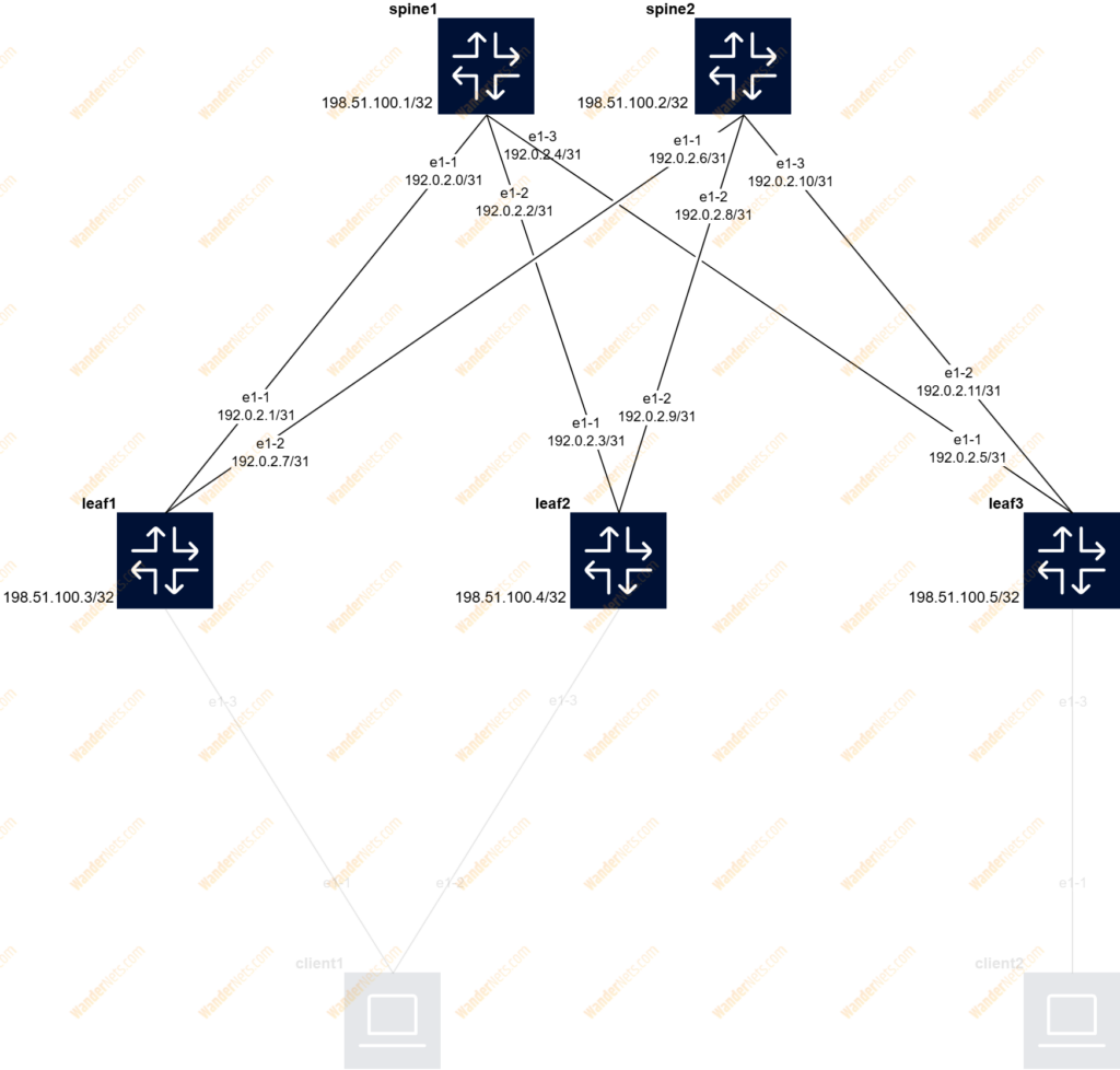
- IP block 192.0.2.0/24 (TEST-NET-1) divided into /31 subnets for point-to-point connections
- IP block 198.51.100.0/24 (TEST-NET-2) for system interfaces
- 4-bytes private ASN
Configuration
In this article, we will present specific configuration commands for the leaf1 node. Those are grouped in batches. If you want to have a full list for each device – spine, leaf, and client, visit our repository with the topology definition.
Interfaces
Let’s start with the IP configuration on point-to-point links. To achieve layer 3 connectivity, create routed subinterface 0 on a particular ethernet interface and associate it with the default network instance.
set / interface ethernet-1/1 description to_spine1
set / interface ethernet-1/1 admin-state enable
set / interface ethernet-1/1 mtu 9412
set / interface ethernet-1/1 ethernet port-speed 10G
set / interface ethernet-1/1 subinterface 0 admin-state enable
set / interface ethernet-1/1 subinterface 0 ip-mtu 9362
set / interface ethernet-1/1 subinterface 0 ipv4 admin-state enable
set / interface ethernet-1/1 subinterface 0 ipv4 address 192.0.2.1/31

set / interface ethernet-1/2 description to_spine2
set / interface ethernet-1/2 admin-state enable
set / interface ethernet-1/2 mtu 9412
set / interface ethernet-1/2 ethernet port-speed 10G
set / interface ethernet-1/2 subinterface 0 admin-state enable
set / interface ethernet-1/2 subinterface 0 ip-mtu 9362
set / interface ethernet-1/2 subinterface 0 ipv4 admin-state enable
set / interface ethernet-1/2 subinterface 0 ipv4 address 192.0.2.7/31

set / network-instance default interface ethernet-1/1.0
set / network-instance default interface ethernet-1/2.0
Commands in this article are divided into batches. Complete list is available here.
Now let’s focus on how to configure an interface named system0 (loopback), which will be used later to create iBGP sessions for EVPN, as well as VXLAN Tunnel Endpoint (VTEP). Note that the interface should also be added to the default network instance.
set / interface system0 admin-state enable
set / interface system0 subinterface 0 admin-state enable
set / interface system0 subinterface 0 ipv4 admin-state enable
set / interface system0 subinterface 0 ipv4 address 198.51.100.3/32

set / network-instance default interface system0.0
Once completed we can review basic IP connectivity using the ping command e.g. between leaf1 and spine1.
BFD
Bidirectional Forwarding Detection (SR-Linux supports asynchronous mode) has been used to monitor BGP peers for fast failure detection. First of all, we need to enable BFD at the subinterface level and define a few parameters e.g. rx interval (200ms), tx interval (200ms), and multiplier (3). Then enable the feature in the BGP group context section. Bear in mind that timer values are in microseconds.
set / bfd subinterface ethernet-1/1.0 admin-state enable
set / bfd subinterface ethernet-1/1.0 desired-minimum-transmit-interval 200000
set / bfd subinterface ethernet-1/1.0 required-minimum-receive 200000
set / bfd subinterface ethernet-1/1.0 detection-multiplier 3
set / bfd subinterface ethernet-1/2.0 admin-state enable
set / bfd subinterface ethernet-1/2.0 desired-minimum-transmit-interval 200000
set / bfd subinterface ethernet-1/2.0 required-minimum-receive 200000
set / bfd subinterface ethernet-1/2.0 detection-multiplier 3
BGP
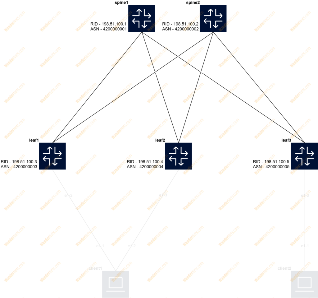
As eBGP has been selected, we need to configure BGP peering between each leaf and spine switch to announce the IP address of the system interface. The import and export policy created restricts the advertising and installation of received routes to only loopback prefixes. In the diagram, you can find info on how we allocate the ASN numbers and Router-IDs. We prefer to use the loopback interface as Router-ID so it is consistent and predictable.
The BGP context is visible in the default network instance, and some parameters like ASN, Router-ID, and AFI/SAFI can be enabled as general:
set / network-instance default protocols bgp admin-state enable
set / network-instance default protocols bgp autonomous-system 4200000003
set / network-instance default protocols bgp router-id 198.51.100.3
set / network-instance default protocols bgp afi-safi ipv4-unicast admin-state enable
If there is more than one spine switch, it is good to create a group – underlay_spine that shares a similar configuration, such as routing policy, BFD, etc.
set / network-instance default protocols bgp group underlay_spine admin-state enable set / network-instance default protocols bgp group underlay_spine description underlay_network
set / network-instance default protocols bgp group underlay_spine export-policy [ export-peers]
set / network-instance default protocols bgp group underlay_spine import-policy [ import-peers]
set / network-instance default protocols bgp group underlay_spine failure-detection enable-bfd true
set / network-instance default protocols bgp group underlay_spine failure-detection fast-failover true
Import and Export routing policy configuration:
set / routing-policy prefix-set peers prefix 198.51.100.0/24 mask-length-range 32..32
set / routing-policy policy export-peers default-action policy-result reject
set / routing-policy policy export-peers statement 10 match prefix-set peers
set / routing-policy policy export-peers statement 10 action policy-result accept
set / routing-policy policy import-peers default-action policy-result reject
set / routing-policy policy import-peers statement 10 match prefix-set peers
set / routing-policy policy import-peers statement 10 action policy-result accept
Finally, the BGP peer configuration:
set / network-instance default protocols bgp neighbor 192.0.2.0 admin-state enable
set / network-instance default protocols bgp neighbor 192.0.2.0 peer-as 4200000001
set / network-instance default protocols bgp neighbor 192.0.2.0 peer-group underlay_spine

set / network-instance default protocols bgp neighbor 192.0.2.6 admin-state enable
set / network-instance default protocols bgp neighbor 192.0.2.6 peer-as 4200000002
set / network-instance default protocols bgp neighbor 192.0.2.6 peer-group underlay_spine
ECMP
To enable equal cost multipathing for VTEPs, additional configuration must be performed within the BGP context. In our case, the maximum-paths parameter is set to 2 as two spine switches are in IP Fabric:
set / network-instance default protocols bgp afi-safi ipv4-unicast multipath allow-multiple-as true
set / network-instance default protocols bgp afi-safi ipv4-unicast multipath maximum-paths 2
Verification
Before we move forward with the configuration of the overlay network, it will be good to review the status of the IP Clos network using a few commands. Let’s start with a simple ping from leaf, checking p2p connections to both spine switches:
A:leaf1# ping 192.0.2.0 network-instance default -c 5
Using network instance default
PING 192.0.2.0 (192.0.2.0) 56(84) bytes of data.
64 bytes from 192.0.2.0: icmp_seq=1 ttl=64 time=2.41 ms
64 bytes from 192.0.2.0: icmp_seq=2 ttl=64 time=2.91 ms
64 bytes from 192.0.2.0: icmp_seq=3 ttl=64 time=3.03 ms
64 bytes from 192.0.2.0: icmp_seq=4 ttl=64 time=2.98 ms
64 bytes from 192.0.2.0: icmp_seq=5 ttl=64 time=3.18 ms

--- 192.0.2.0 ping statistics ---
5 packets transmitted, 5 received, 0% packet loss, time 4005ms
rtt min/avg/max/mdev = 2.411/2.901/3.176/0.260 ms

--{ running }--[  ]--
A:leaf1# ping 192.0.2.6 network-instance default -c 5
Using network instance default
PING 192.0.2.6 (192.0.2.6) 56(84) bytes of data.
64 bytes from 192.0.2.6: icmp_seq=1 ttl=64 time=3.63 ms
64 bytes from 192.0.2.6: icmp_seq=2 ttl=64 time=3.51 ms
64 bytes from 192.0.2.6: icmp_seq=3 ttl=64 time=4.03 ms
64 bytes from 192.0.2.6: icmp_seq=4 ttl=64 time=4.01 ms
64 bytes from 192.0.2.6: icmp_seq=5 ttl=64 time=3.92 ms

--- 192.0.2.6 ping statistics ---
5 packets transmitted, 5 received, 0% packet loss, time 4005ms
rtt min/avg/max/mdev = 3.514/3.819/4.026/0.207 ms
To verify the BFD status for a network instance you can use the following command:
A:leaf1# info from state bfd network-instance default peer 16385
    bfd {
        network-instance default {
            peer 16385 {
                oper-state up
                local-address 192.0.2.1
                remote-address 192.0.2.0
                remote-discriminator 16386
                subscribed-protocols BGP
                session-state UP
                remote-session-state UP
                last-state-transition "2025-04-13T09:13:18.324Z (2 days ago)"
                failure-transitions 0
                local-diagnostic-code NO_DIAGNOSTIC
                remote-diagnostic-code NO_DIAGNOSTIC
                remote-minimum-receive-interval 1000000
                remote-control-plane-independent false
                active-transmit-interval 1000000
                active-receive-interval 1000000
                remote-multiplier 3
                async {
                    last-packet-transmitted "2025-04-15T18:25:00.830Z (4 seconds ago)"
                    last-packet-received "2025-04-15T18:25:00.354Z (5 seconds ago)"
                    transmitted-packets 267173
                    received-packets 267163
                    up-transitions 1
                }
            }
        }
    }
If you look at the command result, the BFD session for eBGP towards spine1 is up and running, we are sending and receiving BFD messages.
Next, let’s take a look at the status of the BGP neighbors to verify what we are receiving:
A:leaf1# show network-instance default protocols bgp neighbor 192.*
---------------------------------------------------------------------------------------------------------------------------------------------------------------------------------------------------
BGP neighbor summary for network-instance "default"
Flags: S static, D dynamic, L discovered by LLDP, B BFD enabled, - disabled, * slow
---------------------------------------------------------------------------------------------------------------------------------------------------------------------------------------------------
---------------------------------------------------------------------------------------------------------------------------------------------------------------------------------------------------
+---------------------+-------------------------------+---------------------+-------+-----------+-----------------+-----------------+---------------+-------------------------------+
|      Net-Inst       |             Peer              |        Group        | Flags |  Peer-AS  |      State      |     Uptime      |   AFI/SAFI    |        [Rx/Active/Tx]         |
+=====================+===============================+=====================+=======+===========+=================+=================+===============+===============================+
| default             | 192.0.2.0                     | underlay_spine      | SB    | 420000000 | established     | 2d:9h:10m:47s   | ipv4-unicast  | [3/3/2]                       |
|                     |                               |                     |       | 1         |                 |                 |               |                               |
| default             | 192.0.2.6                     | underlay_spine      | SB    | 420000000 | established     | 2d:9h:10m:46s   | ipv4-unicast  | [3/3/4]                       |
|                     |                               |                     |       | 2         |                 |                 |               |                               |
+---------------------+-------------------------------+---------------------+-------+-----------+-----------------+-----------------+---------------+-------------------------------+
---------------------------------------------------------------------------------------------------------------------------------------------------------------------------------------------------
Summary:
4 configured neighbors, 4 configured sessions are established, 0 disabled peers
0 dynamic peers
We can also verify what prefixes we are advertising:
A:leaf1# show network-instance default protocols bgp neighbor 192.0.2.0 advertised-routes ipv4
----------------------------------------------------------------------------------------------------------------------------------------------------------------------------------------------------------------------------------------------------------------------------------
Peer        : 192.0.2.0, remote AS: 4200000001, local AS: 4200000003
Type        : static
Description : None
Group       : underlay_spine
----------------------------------------------------------------------------------------------------------------------------------------------------------------------------------------------------------------------------------------------------------------------------------
Origin codes: i=IGP, e=EGP, ?=incomplete
+------------------------------------------------------------------------------------------------------------------------------------------------------------------------------------------------------------------------------------------------------------------------------+
|                     Network                                      Path-id                          Next Hop                     MED                                               LocPref                                             AsPath                   Origin         |
+==============================================================================================================================================================================================================================================================================+
| 198.51.100.2/32                                    0                                      192.0.2.1                             -                                                                                           [4200000003, 4200000002]             i           |
| 198.51.100.3/32                                    0                                      192.0.2.1                             -                                                                                           [4200000003]                         i           |
+------------------------------------------------------------------------------------------------------------------------------------------------------------------------------------------------------------------------------------------------------------------------------+
----------------------------------------------------------------------------------------------------------------------------------------------------------------------------------------------------------------------------------------------------------------------------------
2 advertised BGP routes
----------------------------------------------------------------------------------------------------------------------------------------------------------------------------------------------------------------------------------------------------------------------------------
Finally, let’s check the routing table, note that there are two entries per remote system interface – leaf2 and leaf3 as a result of enabling ECMP:
A:leaf1# show network-instance default route-table ipv4-unicast prefix 198.*
---------------------------------------------------------------------------------------------------------------------------------------------------------------------------------------------------
IPv4 unicast route table of network instance default
---------------------------------------------------------------------------------------------------------------------------------------------------------------------------------------------------
+---------------------------+-------+------------+----------------------+----------+----------+---------+------------+-----------------+-----------------+-----------------+----------------------+
|          Prefix           |  ID   | Route Type |     Route Owner      |  Active  |  Origin  | Metric  |    Pref    | Next-hop (Type) |    Next-hop     | Backup Next-hop |   Backup Next-hop    |
|                           |       |            |                      |          | Network  |         |            |                 |    Interface    |     (Type)      |      Interface       |
|                           |       |            |                      |          | Instance |         |            |                 |                 |                 |                      |
+===========================+=======+============+======================+==========+==========+=========+============+=================+=================+=================+======================+
| 198.51.100.1/32           | 0     | bgp        | bgp_mgr              | True     | default  | 0       | 170        | 192.0.2.0/31 (i | ethernet-1/1.0  |                 |                      |
|                           |       |            |                      |          |          |         |            | ndirect/local)  |                 |                 |                      |
| 198.51.100.2/32           | 0     | bgp        | bgp_mgr              | True     | default  | 0       | 170        | 192.0.2.6/31 (i | ethernet-1/2.0  |                 |                      |
|                           |       |            |                      |          |          |         |            | ndirect/local)  |                 |                 |                      |
| 198.51.100.3/32           | 7     | host       | net_inst_mgr         | True     | default  | 0       | 0          | None (extract)  | None            |                 |                      |
| 198.51.100.4/32           | 0     | bgp        | bgp_mgr              | True     | default  | 0       | 170        | 192.0.2.0/31 (i | ethernet-1/1.0  |                 |                      |
|                           |       |            |                      |          |          |         |            | ndirect/local)  | ethernet-1/2.0  |                 |                      |
|                           |       |            |                      |          |          |         |            | 192.0.2.6/31 (i |                 |                 |                      |
|                           |       |            |                      |          |          |         |            | ndirect/local)  |                 |                 |                      |
| 198.51.100.5/32           | 0     | bgp        | bgp_mgr              | True     | default  | 0       | 170        | 192.0.2.0/31 (i | ethernet-1/1.0  |                 |                      |
|                           |       |            |                      |          |          |         |            | ndirect/local)  | ethernet-1/2.0  |                 |                      |
|                           |       |            |                      |          |          |         |            | 192.0.2.6/31 (i |                 |                 |                      |
|                           |       |            |                      |          |          |         |            | ndirect/local)  |                 |                 |                      |
+---------------------------+-------+------------+----------------------+----------+----------+---------+------------+-----------------+-----------------+-----------------+----------------------+
---------------------------------------------------------------------------------------------------------------------------------------------------------------------------------------------------
---------------------------------------------------------------------------------------------------------------------------------------------------------------------------------------------------
Overlay Network/EVPN/VXLAN
On top of IP Fabric, an overlay network has been built using EVPN (MP-BGP extension) as the Control Plane and VXLAN as the Data Plane to create L2 (mac-vrf), and L3 (ip-vrf) services for tenants. BGP route reflectors were enabled on the spine switches for better scalability and to avoid the configuration of full mesh iBGP peering. The RR cluster-id is constructed based on the IP address of the system interface. EVPN multihoming (LAG) has been implemented based on Ethernet Segment (ES). Host (CE) is connected to both leaf switches in an active-active manner, which means that traffic will be balanced across both uplinks.
Configuration
iBGP
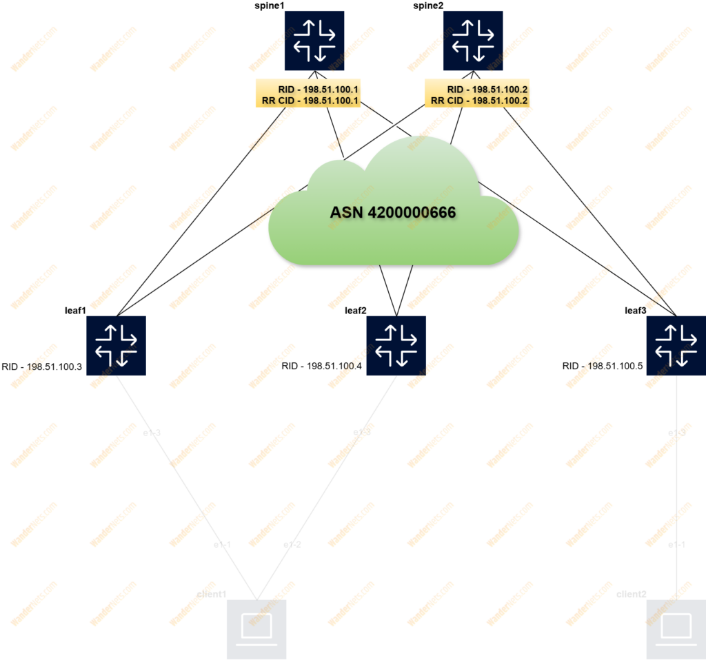
In this section, we will show how to configure the EVPN address family and Route Reflector. This time, BGP peering is done between the system interface IP address of the leaf switch and spine to advertise and receive EVPN routes within the same tenant. In the default network instance, we need to create group named overlay_spine to share the same iBGP settings, below is the configuration for leaf1:
set / network-instance default protocols bgp group overlay_spine admin-state enable
set / network-instance default protocols bgp group overlay_spine failure-detection enable-bfd true
set / network-instance default protocols bgp group overlay_spine failure-detection fast-failover true
set / network-instance default protocols bgp group overlay_spine afi-safi evpn admin-state enable
set / network-instance default protocols bgp group overlay_spine afi-safi ipv4-unicast admin-state disable

set / network-instance default protocols bgp group overlay_spine local-as as-number 4200000666
set / network-instance default protocols bgp group overlay_spine transport local-address 198.51.100.3

set / network-instance default protocols bgp neighbor 198.51.100.1 admin-state enable
set / network-instance default protocols bgp neighbor 198.51.100.1 peer-as 4200000666
set / network-instance default protocols bgp neighbor 198.51.100.1 peer-group overlay_spine
set / network-instance default protocols bgp neighbor 198.51.100.2 admin-state enable
set / network-instance default protocols bgp neighbor 198.51.100.2 peer-as 4200000666
set / network-instance default protocols bgp neighbor 198.51.100.2 peer-group overlay_spine
To enable route reflector on the spine, we need to add two additional lines in the group configuration context, below configuration for spine1:
set / network-instance default protocols bgp group overlay_leaf route-reflector client true
set / network-instance default protocols bgp group overlay_leaf route-reflector cluster-id 198.51.100.1
Now leafs receive the same updates from each RR, so if one of the spines fails it still receives EVPN updates.
VXLAN
Let’s focus on how to create a VXLAN tunnel interface for the bridge and routing domain, which will later be associated with mac-vrf and ip-vrf. Both are described in RFC9135. In the case of layer 2, the VXLAN interface is constructed based on the VLAN ID. A similar approach for VNI and EVI:
set / tunnel-interface vxlan1 vxlan-interface 111 type bridged
set / tunnel-interface vxlan1 vxlan-interface 111 ingress vni 111
set / tunnel-interface vxlan1 vxlan-interface 222 type bridged
set / tunnel-interface vxlan1 vxlan-interface 222 ingress vni 222
In terms of layer 3, the VXLAN interface is constructed based on the RT. A similar approach for VNI and EVI:
set / tunnel-interface vxlan1 vxlan-interface 666 type routed
set / tunnel-interface vxlan1 vxlan-interface 666 ingress vni 666
LAG
Below are a few commands for creating LAG trunk interface, enabling LACP, and adding a physical interface to it:
set / interface lag1 description server1
set / interface lag1 admin-state enable
set / interface lag1 mtu 9216
set / interface lag1 vlan-tagging true
set / interface lag1 subinterface 111 type bridged
set / interface lag1 subinterface 111 admin-state enable
set / interface lag1 subinterface 111 vlan encap single-tagged vlan-id 111
set / interface lag1 subinterface 222 type bridged
set / interface lag1 subinterface 222 admin-state enable
set / interface lag1 subinterface 222 vlan encap single-tagged vlan-id 222

set / interface lag1 lag lag-type lacp
set / interface lag1 lag member-speed 10G
set / interface lag1 lag lacp interval FAST
set / interface lag1 lag lacp lacp-mode ACTIVE
set / interface lag1 lag lacp admin-key 1
set / interface lag1 lag lacp system-id-mac 0A:0A:0A:0A:0A:0A
set / interface lag1 lag lacp system-priority 1

set / interface ethernet-1/3 description to_server
set / interface ethernet-1/3 admin-state enable
set / interface ethernet-1/3 ethernet aggregate-id lag1
set / interface ethernet-1/3 ethernet port-speed 10G
EVPN Multihoming
Our topology supports multi-homing based on EVPN, so the two leafs will synchronize the status of the attached client. To make this happen, the Ethernet segment concept has been used. You can find more information about it in RFC 7432. A unique network-wide Ethernet Segment Identifier (ESI) should be created. RFC 7432 defines five ES types, but SR-Linux currently supports type 0 (this type indicates an arbitrary 9-octet ESI value that is managed and configured by the network operator/administrator). How to construct the ESI is up to you, in our case, we simply used multiples of 10 starting from octet 2 to 9 and on the last octet lag-id towards CE (lag-1).
ES configuration is available under the system network instance:
set / system network-instance protocols evpn ethernet-segments bgp-instance 1 ethernet-segment ES-1 admin-state enable
set / system network-instance protocols evpn ethernet-segments bgp-instance 1 ethernet-segment ES-1 esi 00:10:10:10:10:10:10:10:10:01
set / system network-instance protocols evpn ethernet-segments bgp-instance 1 ethernet-segment ES-1 multi-homing-mode all-active
set / system network-instance protocols evpn ethernet-segments bgp-instance 1 ethernet-segment ES-1 interface lag1
The default Designated Forwarder (DF) algorithm has been changed from a service carving to a preference algorithm, which is described in the Preference-based EVPN DF Election IETF. The leaf switch with the highest preference is DF.
set / system network-instance protocols evpn ethernet-segments bgp-instance 1 ethernet-segment ES-1 df-election algorithm type preference
set / system network-instance protocols evpn ethernet-segments bgp-instance 1 ethernet-segment ES-1 df-election algorithm preference-alg preference-value 100
To prevent the problem of blackholing and to avoid the impact on services if the previous DF leaf returns, two functions have been enabled:
set / system network-instance protocols evpn ethernet-segments bgp-instance 1 ethernet-segment ES-1 df-election algorithm preference-alg capabilities ac-df include
set / system network-instance protocols evpn ethernet-segments bgp-instance 1 ethernet-segment ES-1 df-election algorithm preference-alg capabilities non-revertive true
set / system network-instance protocols bgp-vpn bgp-instance 1
MAC-VRF
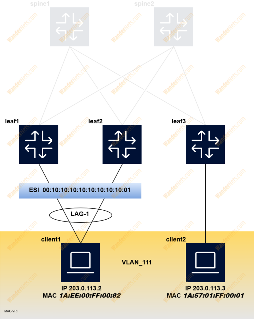
The network instance named VLAN_111 is used as a broadcast domain for VLAN ID 111 and is used to build a bridge table for MAC addresses learned both classically and via EVPN:
set / network-instance VLAN_111 type mac-vrf
set / network-instance VLAN_111 admin-state enable
The IRB interface will be described later, the following configuration must be performed to associate ip-vrf with mac-vrf:
set / network-instance VLAN_111 interface irb1.111VXLAN interface and LAG interface should be added to mac-vrf instance:
set / network-instance VLAN_111 vxlan-interface vxlan1.111
set / network-instance VLAN_111 interface lag1.111
Last but not least, to advertise locally learned mac addresses to remote leafs some EVPN configurations need to be done under two sections:
set / network-instance VLAN_111 protocols bgp-evpn bgp-instance 1 admin-state enable
set / network-instance VLAN_111 protocols bgp-evpn bgp-instance 1 vxlan-interface vxlan1.111
set / network-instance VLAN_111 protocols bgp-evpn bgp-instance 1 evi 111
set / network-instance VLAN_111 protocols bgp-evpn bgp-instance 1 ecmp 2
Note that Route Target is constructed based on AS number and VLAN ID.
set / network-instance VLAN_111 protocols bgp-vpn bgp-instance 1 route-target export-rt target:4200000666:111
set / network-instance VLAN_111 protocols bgp-vpn bgp-instance 1 route-target import-rt target:4200000666:111
IRB
The IRB (Integrated Routing and Bridging Interface) is described in RFC 9135 and is used to virtually connect mac-vrf to ip-vrf and act as a gateway in terms of inter-vlan routing:
set / interface irb1 admin-state enable
set / interface irb1 subinterface 111 admin-state enable
set / interface irb1 subinterface 111 ip-mtu 9000
set / interface irb1 subinterface 111 ipv4 admin-state enable
set / interface irb1 subinterface 111 ipv4 address 203.0.113.1/25 anycast-gw true
set / interface irb1 subinterface 111 ipv4 arp host-route populate dynamic
set / interface irb1 subinterface 111 anycast-gw virtual-router-id 111
Note that anycast-gw has been enabled on two leaf switches to share the same IP configuration. If SR-Linux detects a duplicate IP address, it will not be installed in the routing table.
IP-VRF
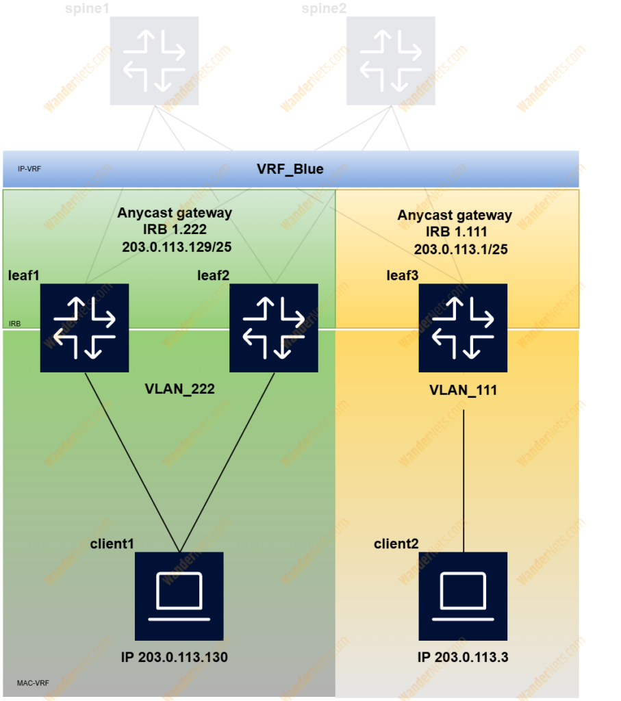
To enable virtual routing between subnets, we need to create an ip-vrf network instance. On leaf1 and leaf2, you can find an instance named VRF_Blue for two tenants: 203.0.113.0/25 (irb1.111) and 203.0.113.128/25 (irb1.222), leaf3 has only one tenant 203.0.113.0/25 (irb1.111) just to show how routing information is distributed between leaf switches. The EVPN route type 5 is used for ip-vrf to ip-vrf, and more details on how ip prefixes are advertised can be found in RFC 9136.
set / network-instance VRF_Blue type ip-vrf
set / network-instance VRF_Blue admin-state enable
The VXLAN tunnel interface (type routed) should be added to the configuration, as we have decided to use a symmetric IRB model.
set / network-instance VRF_Blue interface irb1.111
set / network-instance VRF_Blue vxlan-interface vxlan1.666
To advertise local IP prefixes to remote leafs some EVPN configurations need to be done under two sections (BGP-EVPN & BGP-VPN):
set / network-instance VRF_Blue protocols bgp-evpn bgp-instance 1 vxlan-interface vxlan1.666
set / network-instance VRF_Blue protocols bgp-evpn bgp-instance 1 evi 666
set / network-instance VRF_Blue protocols bgp-evpn bgp-instance 1 ecmp 2
set / network-instance VRF_Blue protocols bgp-vpn bgp-instance 1 route-target export-rt target:4200000666:666
set / network-instance VRF_Blue protocols bgp-vpn bgp-instance 1 route-target import-rt target:4200000666:666
As SR-Linux supports only an Interface-Less model so route target for import and export are mandatory, RT is constructed based on AS number and random ID.
Verification
iBGP
Let’s start with checking iBGP sessions from leaf1 toward both Route Reflectors (198.51.100.1 and 198.51.100.2):
A:leaf1# show network-instance default protocols bgp neighbor 198.*
---------------------------------------------------------------------------------------------------------------------------------------------------------------------------------------------------
BGP neighbor summary for network-instance "default"
Flags: S static, D dynamic, L discovered by LLDP, B BFD enabled, - disabled, * slow
---------------------------------------------------------------------------------------------------------------------------------------------------------------------------------------------------
---------------------------------------------------------------------------------------------------------------------------------------------------------------------------------------------------
+---------------------+-------------------------------+---------------------+-------+-----------+-----------------+-----------------+---------------+-------------------------------+
|      Net-Inst       |             Peer              |        Group        | Flags |  Peer-AS  |      State      |     Uptime      |   AFI/SAFI    |        [Rx/Active/Tx]         |
+=====================+===============================+=====================+=======+===========+=================+=================+===============+===============================+
| default             | 198.51.100.1                  | overlay_spine       | SB    | 420000066 | established     | 2d:7h:21m:15s   | evpn          | [20/20/19]                    |
|                     |                               |                     |       | 6         |                 |                 |               |                               |
| default             | 198.51.100.2                  | overlay_spine       | SB    | 420000066 | established     | 2d:7h:21m:15s   | evpn          | [20/0/19]                     |
|                     |                               |                     |       | 6         |                 |                 |               |                               |
+---------------------+-------------------------------+---------------------+-------+-----------+-----------------+-----------------+---------------+-------------------------------+
---------------------------------------------------------------------------------------------------------------------------------------------------------------------------------------------------
Summary:
4 configured neighbors, 4 configured sessions are established, 0 disabled peers
0 dynamic peers
VXLAN
Below outcome from two commands that show us the VXLAN tunnel configuration:
A:leaf1# show tunnel-interface vxlan1 vxlan-interface brief
---------------------------------------------------------------------------------------------------------------------------------------------------------------------------------------------------
Show report for vxlan-tunnels
---------------------------------------------------------------------------------------------------------------------------------------------------------------------------------------------------
+------------------+-----------------+---------+-------------+------------------+
| Tunnel Interface | VxLAN Interface |  Type   | Ingress VNI | Egress source-ip |
+==================+=================+=========+=============+==================+
| vxlan1           | vxlan1.111      | bridged | 111         | 198.51.100.3/32  |
| vxlan1           | vxlan1.222      | bridged | 222         | 198.51.100.3/32  |
| vxlan1           | vxlan1.666      | routed  | 666         | 198.51.100.3/32  |
+------------------+-----------------+---------+-------------+------------------+
---------------------------------------------------------------------------------------------------------------------------------------------------------------------------------------------------
Summary
  1 tunnel-interfaces, 3 vxlan interfaces
  8 vxlan-destinations, 3 unicast, 0 es, 3 multicast, 2 ip
---------------------------------------------------------------------------------------------------------------------------------------------------------------------------------------------------
A:leaf1# show tunnel vxlan-tunnel all
---------------------------------------------------------------------------------------------------------------------------------------------------------------------------------------------------
Show report for vxlan-tunnels
---------------------------------------------------------------------------------------------------------------------------------------------------------------------------------------------------
+--------------+---------+--------------------------+
| VTEP Address | Index | Last Change |
+==============+=========+==========================+
| 198.51.100.4 | 9630084 | 2025-04-05T15:08:45.000Z |
| 198.51.100.5 | 9630085 | 2025-04-05T15:08:45.000Z |
+--------------+---------+--------------------------+
2 VXLAN tunnels, 2 active, 0 inactive
---------------------------------------------------------------------------------------------------------------------------------------------------------------------------------------------------
LAG
Configuration and LACP state can be revieved using the below command:
A:leaf1# show lag lag1
===================================================================================================================================================================================================
lag1 is up, Aggregate speed 10000 Mbps, min links 1
+-----------------+------------+---------------------------+
|   Member Name   | oper-state |     oper-down-reason      |
+=================+============+===========================+
| ethernet-1/3    | up         |                           |
+-----------------+------------+---------------------------+
---------------------------------------------------------------------------------------------------------------------------------------------------------------------------------------------------
===================================================================================================================================================================================================
  1 LAG interfaces are up, 0 are down
===================================================================================================================================================================================================
To collect LACP-specific configuration, we can use the following command:
A:leaf1# show lag lag1 lacp-state
---------------------------------------------------------------------------------------------------------------------------------------------------------------------------------------------------
LACP State for lag1
---------------------------------------------------------------------------------------------------------------------------------------------------------------------------------------------------
Lag Id         : lag1
Interval       : FAST
Mode           : ACTIVE
System Id      : 0A:0A:0A:0A:0A:0A
System Priority: 1
+---------------+----------------+----------------+----------------+----------------+----------------+----------------+----------------+----------------+----------------+----------------+
|    Members    |   Oper state   |    Activity    |    Timeout     |     State      |   System Id    |    Oper key    |   Partner Id   |  Partner Key   |    Port No     |  Partner Port  |
|               |                |                |                |                |                |                |                |                |                |       No       |
+===============+================+================+================+================+================+================+================+================+================+================+
| ethernet-1/3  | up             | ACTIVE         | SHORT          | IN_SYNC/True/T | 0A:0A:0A:0A:0A | 1              | CC:CC:CC:CC:CC | 1              | 1              | 1              |
|               |                |                |                | rue/True       | :0A            |                | :CC            |                |                |                |
+---------------+----------------+----------------+----------------+----------------+----------------+----------------+----------------+----------------+----------------+----------------+
---------------------------------------------------------------------------------------------------------------------------------------------------------------------------------------------------
Take a look at the State column where:
IN_SYNC means that the far end (client) received a consistent system-id and key, the remaining options are for aggregation, collecting, and distributing. Based on the outcome we can say that lag is fully operational.
ESI
Now, it would be a good idea to check the status of the ethernet segment, associated mac-vrf instances, as well as which leaf switch is elected as DF:
A:leaf1# show system network-instance ethernet-segments ES-1
---------------------------------------------------------------------------------------------------------------------------------------------------------------------------------------------------
ES-1 is up, all-active
  ESI      : 00:10:10:10:10:10:10:10:10:01
  Alg      : preference
  Peers    : 198.51.100.4
  Interface: lag1
  Next-hop : N/A
  evi      : N/A
  Network-instances:
     VLAN_111
      Candidates : 198.51.100.3, 198.51.100.4 (DF)
      Interface : lag1.111
  Network-instances:
     VLAN_222
      Candidates : 198.51.100.3, 198.51.100.4 (DF)
      Interface : lag1.222
---------------------------------------------------------------------------------------------------------------------------------------------------------------------------------------------------
Summary
1 Ethernet Segments Up
0 Ethernet Segments Down
---------------------------------------------------------------------------------------------------------------------------------------------------------------------------------------------------
MAC-VRF
Finally, let’s check how the bridge table looks in terms of mac addresses.
A:leaf1# show network-instance VLAN_111 bridge-table mac-table all
---------------------------------------------------------------------------------------------------------------------------------------------------------------------------------------------------
Mac-table of network instance VLAN_111
---------------------------------------------------------------------------------------------------------------------------------------------------------------------------------------------------
+--------------------+-------------------------------------------------------+------------+-----------------+---------+--------+-------------------------------------------------------+
|      Address       |                      Destination                      | Dest Index |      Type       | Active  | Aging  |                      Last Update                      |
+====================+=======================================================+============+=================+=========+========+=======================================================+
| 00:00:5E:00:01:6F  | irb-interface                                         | 0          | irb-interface-  | true    | N/A    | 2025-04-05T15:07:53.000Z                              |
|                    |                                                       |            | anycast         |         |        |                                                       |
| 1A:02:00:FF:00:82  | lag1.111                                              | 5          | learnt          | true    | 254    | 2025-04-05T15:13:41.000Z                              |
| 1A:3B:02:FF:00:42  | irb-interface                                         | 0          | irb-interface   | true    | N/A    | 2025-04-05T15:07:53.000Z                              |
| 1A:A2:04:FF:00:42  | vxlan-interface:vxlan1.111 vtep:198.51.100.5 vni:111  | 9630104    | evpn-static     | true    | N/A    | 2025-04-05T15:08:45.000Z                              |
| 1A:C3:03:FF:00:42  | vxlan-interface:vxlan1.111 vtep:198.51.100.4 vni:111  | 9630103    | evpn-static     | true    | N/A    | 2025-04-05T15:08:45.000Z                              |
| 1A:CE:01:FF:00:01  | vxlan-interface:vxlan1.111 vtep:198.51.100.5 vni:111  | 9630104    | evpn            | true    | N/A    | 2025-04-05T15:08:45.000Z                              |
+--------------------+-------------------------------------------------------+------------+-----------------+---------+--------+-------------------------------------------------------+
Total Irb Macs                 :    1 Total    1 Active
Total Static Macs              :    0 Total    0 Active
Total Duplicate Macs           :    0 Total    0 Active
Total Learnt Macs              :    1 Total    1 Active
Total Evpn Macs                :    1 Total    1 Active
Total Evpn static Macs         :    2 Total    2 Active
Total Irb anycast Macs         :    1 Total    1 Active
Total Proxy Antispoof Macs     :    0 Total    0 Active
Total Reserved Macs            :    0 Total    0 Active
Total Eth-cfm Macs             :    0 Total    0 Active
Total Irb Vrrps                :    0 Total    0 Active
The entry for mac address 1A:EE:00:FF:00:82 is type learnt, which means that leaf1 has learned it from the incoming frame on lag-1. The destination for mac address 1A:57:01:FF:00:01 is the VXLAN interface with VTEP IP address and specific VNI, meaning that leaf1 learned it via EVPN.
If you look at the bridge table on leaf3, instead of VTEP, ESI will be as destination for mac address 1A:EE:00:FF:00:82
A:leaf3# show network-instance VLAN_111 bridge-table mac-table all
---------------------------------------------------------------------------------------------------------------------------------------------------------------------------------------------------
Mac-table of network instance VLAN_111
---------------------------------------------------------------------------------------------------------------------------------------------------------------------------------------------------
+--------------------+-------------------------------------------------------+------------+-----------------+---------+--------+-------------------------------------------------------+
|      Address       |                      Destination                      | Dest Index |      Type       | Active  | Aging  |                      Last Update                      |
+====================+=======================================================+============+=================+=========+========+=======================================================+
| 00:00:5E:00:01:6F  | irb-interface                                         | 0          | irb-interface-  | true    | N/A    | 2025-04-10T15:54:57.000Z                              |
|                    |                                                       |            | anycast         |         |        |                                                       |
| 1A:69:04:FF:00:42  | irb-interface                                         | 0          | irb-interface   | true    | N/A    | 2025-04-10T15:54:57.000Z                              |
| 1A:92:01:FF:00:01  | ethernet-1/3.111                                      | 3          | learnt          | true    | 226    | 2025-04-10T16:01:00.000Z                              |
| 1A:A1:02:FF:00:42  | vxlan-interface:vxlan1.111 vtep:198.51.100.3 vni:111  | 10813266   | evpn-static     | true    | N/A    | 2025-04-10T15:55:48.000Z                              |
| 1A:AD:00:FF:00:82  | vxlan-interface:vxlan1.111                            | 10813267   | evpn            | true    | N/A    | 2025-04-10T15:55:48.000Z                              |
|                    | esi:00:10:10:10:10:10:10:10:10:01                     |            |                 |         |        |                                                       |
| 1A:EA:03:FF:00:42  | vxlan-interface:vxlan1.111 vtep:198.51.100.4 vni:111  | 10813265   | evpn-static     | true    | N/A    | 2025-04-10T15:55:48.000Z                              |
+--------------------+-------------------------------------------------------+------------+-----------------+---------+--------+-------------------------------------------------------+
Total Irb Macs                 :    1 Total    1 Active
Total Static Macs              :    0 Total    0 Active
Total Duplicate Macs           :    0 Total    0 Active
Total Learnt Macs              :    1 Total    1 Active
Total Evpn Macs                :    1 Total    1 Active
Total Evpn static Macs         :    2 Total    2 Active
Total Irb anycast Macs         :    1 Total    1 Active
Total Proxy Antispoof Macs     :    0 Total    0 Active
Total Reserved Macs            :    0 Total    0 Active
Total Eth-cfm Macs             :    0 Total    0 Active
Total Irb Vrrps                :    0 Total    0 Active
Using the following commands, we can check which VTEPs are associated with a particular ESI, as well as the MAC addresses connected to the VXLAN interface:
A:leaf3# show tunnel-interface vxlan1 vxlan-interface 111 bridge-table unicast-destinations destination
---------------------------------------------------------------------------------------------------------------------------------------------------------------------------------------------------
Show report for vxlan-interface vxlan1.111 unicast destinations
---------------------------------------------------------------------------------------------------------------------------------------------------------------------------------------------------
Destinations
---------------------------------------------------------------------------------------------------------------------------------------------------------------------------------------------------
+--------------+------------+-------------------+-----------------------------+
| VTEP Address | Egress VNI | Destination-index | Number MACs (Active/Failed) |
+==============+============+===================+=============================+
| 198.51.100.3 | 111        | 10813266          | 1(1/0)                      |
| 198.51.100.4 | 111        | 10813265          | 1(1/0)                      |
+--------------+------------+-------------------+-----------------------------+
---------------------------------------------------------------------------------------------------------------------------------------------------------------------------------------------------
Ethernet Segment Destinations
---------------------------------------------------------------------------------------------------------------------------------------------------------------------------------------------------
+-------------------------------+-------------------+----------------------------+-----------------------------+
|              ESI              | Destination-index |           VTEPs            | Number MACs (Active/Failed) |
+===============================+===================+============================+=============================+
| 00:10:10:10:10:10:10:10:10:01 | 10813267          | 198.51.100.3, 198.51.100.4 | 1(1/0)                      |
+-------------------------------+-------------------+----------------------------+-----------------------------+
---------------------------------------------------------------------------------------------------------------------------------------------------------------------------------------------------
Summary
  3 unicast-destinations, 2 non-es, 1 es
  3 MAC addresses, 3 active, 0 non-active
---------------------------------------------------------------------------------------------------------------------------------------------------------------------------------------------------
A:leaf3# show tunnel-interface vxlan1 vxlan-interface 111 bridge-table mac-table
---------------------------------------------------------------------------------------------------------------------------------------------------------------------------------------------------
MAC table for vxlan-interface vxlan1.111
---------------------------------------------------------------------------------------------------------------------------------------------------------------------------------------------------
+-------------------+--------------+-----+----------+-------------+--------------------------+
| Address | Destination | VNI | Index | Type | Last update |
+===================+==============+=====+==========+=============+==========================+
| 1A:A1:02:FF:00:42 | 198.51.100.3 | 111 | 10813266 | evpn-static | 2025-04-10T15:55:48.000Z |
| 1A:EA:03:FF:00:42 | 198.51.100.4 | 111 | 10813265 | evpn-static | 2025-04-10T15:55:48.000Z |
| 1A:AD:00:FF:00:82 | 198.51.100.3 | 111 | 10813267 | evpn | 2025-04-10T15:55:48.000Z |
| | , | 111 | | | |
| | 198.51.100.4 | | | | |
+-------------------+--------------+-----+----------+-------------+--------------------------+
---------------------------------------------------------------------------------------------------------------------------------------------------------------------------------------------------
Summary
Total evpn macs : 1 Total, 1 Active
Total evpn-static macs : 2 Total, 2 Active
Total macs : 3 Total, 3 Active
---------------------------------------------------------------------------------------------------------------------------------------------------------------------------------------------------
IP-VRF
Before checking the routing table, it would be a good idea to review the type 5 routes that we receive and send to route reflectors:
A:leaf3# show network-instance default protocols bgp neighbor 198.51.100.1 advertised-routes evpn | grep "Type 5 IP Prefix Routes" --after-context 10
Type 5 IP Prefix Routes
+---------------------+--------+----------------+--------------+-----+---------+------+
| Route-distinguisher | Tag-ID |   IP-address   |   Next-Hop   | MED | LocPref | Path |
+=====================+========+================+==============+=====+=========+======+
| 198.51.100.5:666    | 0      | 203.0.113.0/25 | 198.51.100.5 | -   | 100     |      |
| 198.51.100.5:666    | 0      | 203.0.113.3/32 | 198.51.100.5 | -   | 100     |      |
+---------------------+--------+----------------+--------------+-----+---------+------+
---------------------------------------------------------------------------------------------------------------------------------------------------------------------------------------------------
---------------------------------------------------------------------------------------------------------------------------------------------------------------------------------------------------
0 advertised Ethernet Auto-Discovery routes
4 advertised MAC-IP Advertisement routes
A:leaf3# show network-instance default protocols bgp neighbor 198.51.100.1 received-routes evpn | grep "Type 5 IP Prefix Routes" --after-context 10
Type 5 IP Prefix Routes
+--------+---------------------+--------+----------------+--------------+-----+---------+------+
| Status | Route-distinguisher | Tag-ID | IP-address | Next-Hop | MED | LocPref | Path |
+========+=====================+========+================+==============+=====+=========+======+
| u*> | 198.51.100.3:666 | 0 | 203.0.113.0/25 | 198.51.100.3 | - | 100 | |
| u*> | 198.51.100.3:666 | 0 | 203.0.113.128/ | 198.51.100.3 | - | 100 | |
| | | | 25 | | | | |
| u*> | 198.51.100.3:666 | 0 | 203.0.113.2/32 | 198.51.100.3 | - | 100 | |
| u*> | 198.51.100.3:666 | 0 | 203.0.113.130/ | 198.51.100.3 | - | 100 | |
| | | | 32 | | | | |
| u*> | 198.51.100.4:666 | 0 | 203.0.113.0/25 | 198.51.100.4 | - | 100 | |Now, let’s take a look at the routing table:
A:leaf3# show network-instance VRF_Blue route-table all
-----------------------------------------------------------------------------------------------------------------------------------------------------------------------------------------------------------------------
IPv4 unicast route table of network instance VRF_Blue
-----------------------------------------------------------------------------------------------------------------------------------------------------------------------------------------------------------------------
+-------------------------------+-------+------------+----------------------+----------+----------+---------+------------+-------------------+-------------------+-------------------+--------------------------------+
|            Prefix             |  ID   | Route Type |     Route Owner      |  Active  |  Origin  | Metric  |    Pref    |  Next-hop (Type)  |     Next-hop      |  Backup Next-hop  |   Backup Next-hop Interface    |
|                               |       |            |                      |          | Network  |         |            |                   |     Interface     |      (Type)       |                                |
|                               |       |            |                      |          | Instance |         |            |                   |                   |                   |                                |
+===============================+=======+============+======================+==========+==========+=========+============+===================+===================+===================+================================+
| 203.0.113.0/25                | 0     | bgp-evpn   | bgp_evpn_mgr         | False    | VRF_Blue | 0       | 170        | 198.51.100.3/32   |                   |                   |                                |
|                               |       |            |                      |          |          |         |            | (indirect/vxlan)  |                   |                   |                                |
|                               |       |            |                      |          |          |         |            | 198.51.100.4/32   |                   |                   |                                |
|                               |       |            |                      |          |          |         |            | (indirect/vxlan)  |                   |                   |                                |
| 203.0.113.0/25                | 4     | local      | net_inst_mgr         | True     | VRF_Blue | 0       | 0          | 203.0.113.1       | irb1.111          |                   |                                |
|                               |       |            |                      |          |          |         |            | (direct)          |                   |                   |                                |
| 203.0.113.1/32                | 4     | host       | net_inst_mgr         | True     | VRF_Blue | 0       | 0          | None (extract)    | None              |                   |                                |
| 203.0.113.2/32                | 0     | bgp-evpn   | bgp_evpn_mgr         | True     | VRF_Blue | 0       | 170        | 198.51.100.3/32   |                   |                   |                                |
|                               |       |            |                      |          |          |         |            | (indirect/vxlan)  |                   |                   |                                |
| 203.0.113.3/32                | 4     | arp-nd     | arp_nd_mgr           | True     | VRF_Blue | 0       | 1          | 203.0.113.3       | irb1.111          |                   |                                |
|                               |       |            |                      |          |          |         |            | (direct)          |                   |                   |                                |
| 203.0.113.127/32              | 4     | host       | net_inst_mgr         | True     | VRF_Blue | 0       | 0          | None (broadcast)  |                   |                   |                                |
| 203.0.113.128/25              | 0     | bgp-evpn   | bgp_evpn_mgr         | True     | VRF_Blue | 0       | 170        | 198.51.100.3/32   |                   |                   |                                |
|                               |       |            |                      |          |          |         |            | (indirect/vxlan)  |                   |                   |                                |
|                               |       |            |                      |          |          |         |            | 198.51.100.4/32   |                   |                   |                                |
|                               |       |            |                      |          |          |         |            | (indirect/vxlan)  |                   |                   |                                |
| 203.0.113.130/32              | 0     | bgp-evpn   | bgp_evpn_mgr         | True     | VRF_Blue | 0       | 170        | 198.51.100.3/32   |                   |                   |                                |
|                               |       |            |                      |          |          |         |            | (indirect/vxlan)  |                   |                   |                                |
+-------------------------------+-------+------------+----------------------+----------+----------+---------+------------+-------------------+-------------------+-------------------+--------------------------------+
-----------------------------------------------------------------------------------------------------------------------------------------------------------------------------------------------------------------------
IPv4 routes total                    : 8
IPv4 prefixes with active routes     : 7
IPv4 prefixes with active ECMP routes: 2
-----------------------------------------------------------------------------------------------------------------------------------------------------------------------------------------------------------------------
Finally, let’s test the connectivity between client1 and client2. The first connectivity check is based on layer 2:
A:client1# ping network-instance default 203.0.113.3 -c 5
Using network instance default
PING 203.0.113.3 (203.0.113.3) 56(84) bytes of data.
64 bytes from 203.0.113.3: icmp_seq=1 ttl=64 time=3.93 ms
64 bytes from 203.0.113.3: icmp_seq=2 ttl=64 time=4.34 ms
64 bytes from 203.0.113.3: icmp_seq=3 ttl=64 time=4.26 ms
64 bytes from 203.0.113.3: icmp_seq=4 ttl=64 time=4.20 ms
64 bytes from 203.0.113.3: icmp_seq=5 ttl=64 time=4.44 ms

--- 203.0.113.3 ping statistics ---
5 packets transmitted, 5 received, 0% packet loss, time 4004ms
rtt min/avg/max/mdev = 3.930/4.235/4.440/0.172 ms
The second one is a layer 3 connection between subnets 203.0.113.128/25 and 203.0.113.0/25:
A:client2# ping network-instance default 203.0.113.130 -c 5
Using network instance default
PING 203.0.113.130 (203.0.113.130) 56(84) bytes of data.
64 bytes from 203.0.113.130: icmp_seq=1 ttl=64 time=4.24 ms
64 bytes from 203.0.113.130: icmp_seq=2 ttl=64 time=3.99 ms
64 bytes from 203.0.113.130: icmp_seq=3 ttl=64 time=4.02 ms
64 bytes from 203.0.113.130: icmp_seq=4 ttl=64 time=4.01 ms
64 bytes from 203.0.113.130: icmp_seq=5 ttl=64 time=3.96 ms

--- 203.0.113.130 ping statistics ---
5 packets transmitted, 5 received, 0% packet loss, time 4004ms
rtt min/avg/max/mdev = 3.960/4.043/4.238/0.099 ms
Summary
There are a lot of steps and even more configuration pieces to remember when configuring Layer 2 Multi-homing with Layer 3 EVPN on Nokia SR-Linux. What’s great about the platform is that this environment can be deployed virtually on your computer, thanks to Containerlab. If you’re curious about how to do that, read our article on Deploying a Nokia SR-Linux MC-LAG Lab in Seconds with Containerlab.
Authors

One thought on “Configure Layer 2 Multi-homing and Layer 3 EVPN on Nokia SR-Linux”